

RF Keyboard Project
I travel a lot for work. Sometimes, I miss PC gaming. To solve this, I decided to build my own custom wireless RF minimal keyboard.
Introduction
When coming into this project, I already had some understanding of the requirements for this keyboard. This keyboard needs to be decently portable and light, and I want to keep it functional enough to play games on — no membrane keyboards here. However, I can't just cut off half the keys. This keyboard will, also, be used for work.
Eventually, I came up with this design.
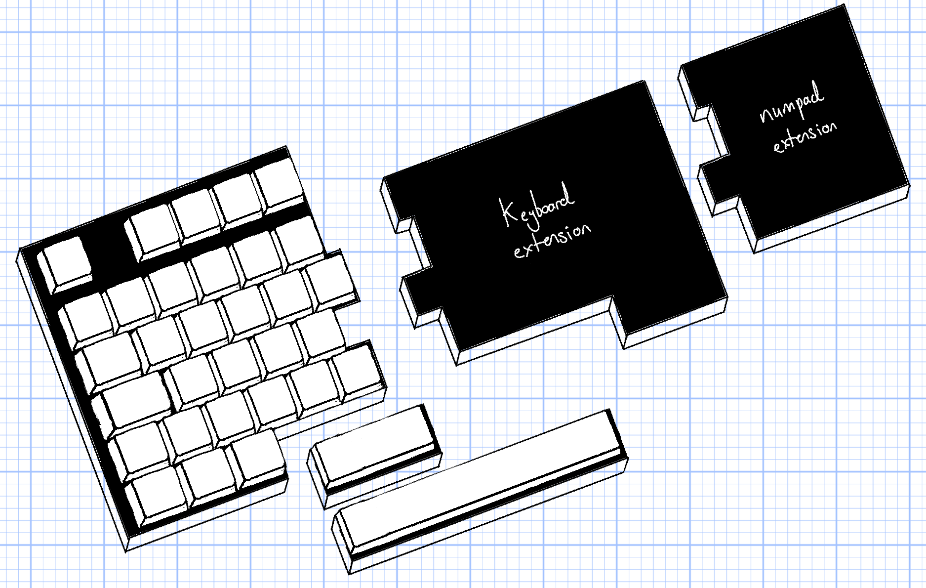
The design will consist of a 'main' (or 'master') keyboard, which will contain the keys I use most often, and an 'auxilary' (or 'slave') keyboard, which will contain the rest of the keys. The two keyboards will be connected magnetically. If I need a full keyboard (or numpad) for work, I can snap-in the module onto the master keyboard. If I just want to play games, I can only take the main keyboard with me.
The keyboards will be connected with magentic pogo pin connectors. This design will allow me to save on battery life in comparison to the traditional split keyboard design. This is because the slave module will not need it's own RF/wireless capabilities, or its own battery, and will use a weaker MCU. Also, it'll be more convenient to have to charge only one keyboard — instead of two. The slave module will get it's power from the master module.
Research
Before we dive into the design, we need to find out what keys to include in our main module, and how we will position them.
Key Selection
First up, I wanted to see what keys I use most often when gaming. I want to make my backpack as light as humanly possible, so I used a keylogger to track my key usage over a few sessions of gaming. The ones I used the most could be added to the 'main' or 'master' custom keyboard, and the ones I used less often could be left out.
Here's the code:
keylogger.py
import os, csv
from pynput import keyboard

class keylogger:
    def __init__(self, data_output_path_relative):
        self.data_output_path : str = data_output_path_relative
        self.filename : str = None
        self.key_counter : dict[str: int] = {}
        self.previously_pressed_key : str = None

    def start(self):

        self.filename = "logger.csv"
        files = os.listdir(self.data_output_path)
        if not self.filename in files:
            # write initial csv header
            with open(os.path.join(self.data_output_path, self.filename), mode='w', newline='') as file:
                writer = csv.writer(file)
                writer.writerow(["key", "counter"])
        else:
            # load existing key counter data
            self.read_data()

        #start logger
        with keyboard.Listener(on_press=self.on_press) as listener:
            listener.join()

    def read_data(self):
        with open(os.path.join(self.data_output_path, self.filename), mode='r') as file:
            reader = csv.reader(file)
            next(reader)  # Skip header
            for row in reader:
                key, counter = row
                self.key_counter[key] = int(counter)

    def write_data(self):
        with open(os.path.join(self.data_output_path, self.filename), mode='w', newline='') as file:
            writer = csv.writer(file)
            writer.writerow(["key", "counter"])
            for key, counter in self.key_counter.items():
                writer.writerow([key, counter])

    def decode_ctrl_char(self, c):
        if isinstance(c, str) and c.startswith(r"\x") and len(c) == 4:
            try:
                value = int(c[2:], 16)  # hex part after \x
                if 1 <= value <= 26:
                    return f"ctrl_l+{chr(value + 96)}"
                return f"ctrl_l+{value}"
            except ValueError:
                pass
        return c
    def on_press(self, key):
        # get the key name
        key_name = []
        try:
            if(str(key).startswith("Key.")):
                raise AttributeError
            key_name.append(str(key)[1:-1])
        except AttributeError:
            key_name.append(str(key.name))

        if r"\x" in key_name[0]:
            key_to_decode = key_name[0]
            key_name=[]
            key_combo = self.decode_ctrl_char(key_to_decode)
            keys = key_combo.split("+")
            if self.previously_pressed_key == "ctrl_l":
                key_name.append(keys[1])
            else:
                key_name.append(keys[0])
                key_name.append(keys[1])
        for k in key_name:
            k = k.lower()
            if (k != self.previously_pressed_key):
                self.previously_pressed_key = k
                print(f"Key pressed: {k}")

            self.read_data()

            if k in self.key_counter:
                self.key_counter[k] += 1
            else:
                self.key_counter[k] = 1

            self.write_data()


if __name__ == "__main__":
    kl = keylogger(data_output_path_relative="data")
    kl.start()
To process the data into a visual format that I could easily understand, I used the Python library Pillow to create a heatmap diagram.
The diagram is comprised of three layered images. The bottom image contains the key boxes, the middle image contains the drawn heatmap, and the top images contains the key labels.
You can download the code and mask images here:
Download Project ZIPFinally, I was left with this heatmap diagram:
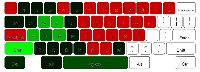
The greener the key, the more I used it. As you can see, the keys I use the most are W, A, S, D, Q, E, Z, X CTRL, SHIFT, and SPACE
This gave me a rough idea of what keys I want to keep. Some less used keys I still kept — like ALT, ESC, numbers 1 through 5, and M.
Understanding Keycap Sizes
Before we start the PCB or 3D design, we need to understand keycap sizes and spacing — informing us on how to space the switches on the PCB.
Switches, themselves, are about 18mm x 18mm with a 5.05mm gap between each switch; resulting in a 19.05mm distance fron centre-to-centre between switches/keycaps.
To help with keycap spacing, keycaps are measured using units (u), with a 1u keycap being a normal key like Q, W, E, or R. Larger keys use the 1u keycap as a refence.
- Backspace2U
- Tab1.5U
- Caps Lock1.75U
- Space6.25U — 7U
- EnterNon-standard
- Left Shift2.25U
- Right Shift1.75U
- Control1.25U
However, not all keyboards follow the size guide. For instance, my Keychron K10 pro's left shift key is 1.25u and the right shift is ~2.6u.
There are also different keyboard layouts:
ANSI, ISO, and JIS
We'll definitely not use JIS because that's Japanese Industrial Standard and I'm not Japanese. International Organization for Standardization (why is this the acronym for ISO it should be IOS) is what I use and is what is most common in Europe — so we'll go with that.
Now, keycap size isn't the only factor to consider. We, also, need to consider keycap height, profile, and row sculpting — the keycap profile.
If you're interest in keycaps (for some reason) you can look into the above link; however, I'll save you the snoozefest and say we'll go with OEM keycaps. That's what I'm used to, and that's what I want. Although, I reserve the right to switch to Cherry! These switches are most common and consistent across manufactuers.
Alright. It's sorted then. ISO layout and OEM keycap profile.
Firmware
No need to reinvent the wheel here.
I could spend the next few months writing my own custom USB HID firmware from scratch, or I could use ZMK — an open source wireless keyboard firmware. ZMK supports both bluetooth and RF, so it will be perfect. ZMK also allows for a lot of customisation, so I can add macros and complex key combinations if I want to.
PCB design
First, I will design the PCB for the master and auxilary modules. With the PCB design, I can get a better idea of how to make the 3D design for the case.
Parts
For the master module, I will be using the nRF52840 'ProMicro' MCU. This MCU dev board has built in bluetooth and 2.4GHz RF capabilities, which is perfect for our use case. Ideally, I want the keyboard to be able to do wired, wireless BLE, and wireless RF. This MCU should be able to allow us to do all three.
For the auxilary modules, I will be using the ATTiny1616 MCU. This MCU is weaker and less capable than the nRF52840, but that's fine. It has built in I2C capabilities, which will allow it to transmit the key presses to the master module.
The communication loop will involve using an active-low input. So, when the auxilary module detected a key press, it'll pull the 'WAKE' signal low, which will wake up the main module. The main module will then request the key data via I2C. I suspect there could be some issues with latency here, but we'll see if it's a problem when we get to prototyping. For now, we pray <3.
Aside from this, we will need components for power management, battery charging, and battery-life indication.
I reserve the right to change this section and communication loop later on. This is just my initial plan based on my current understanding of the project requirements and constraints. It's likely that I'll learn more about the project as I go along, which will inform changes to the design and communication loop. Maybe I don't need slave MCUs and can directly connect the auxilary PCB's key matrix to the master PCB's key matrix. :P
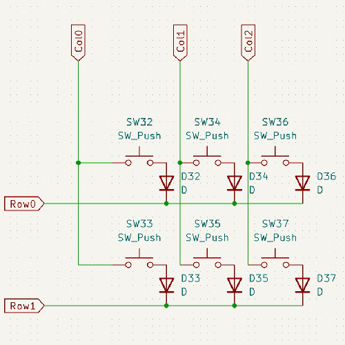
Schematic Design
Switches are connected in rows and columns. When a key is pressed, two signals are activated — one for the row and one for the column. Using this infomation, the MCU can determine which key has been pressed. As for the auxilary modules, these will have their own MCU (ATTiny1616) and will transmit the key pressed to the master using I2C. As the spacebar is one key, it doesn't even need an MCU. It can just have 2 pogo pins to connect to the existing row and column signals on the master PCB.
Prototyping
Before we start this project, we need to create a few prototypes so that I can learn how to program ZMK firmware, and test how the magnetic fit will work.
Prototyping ZMK firmware
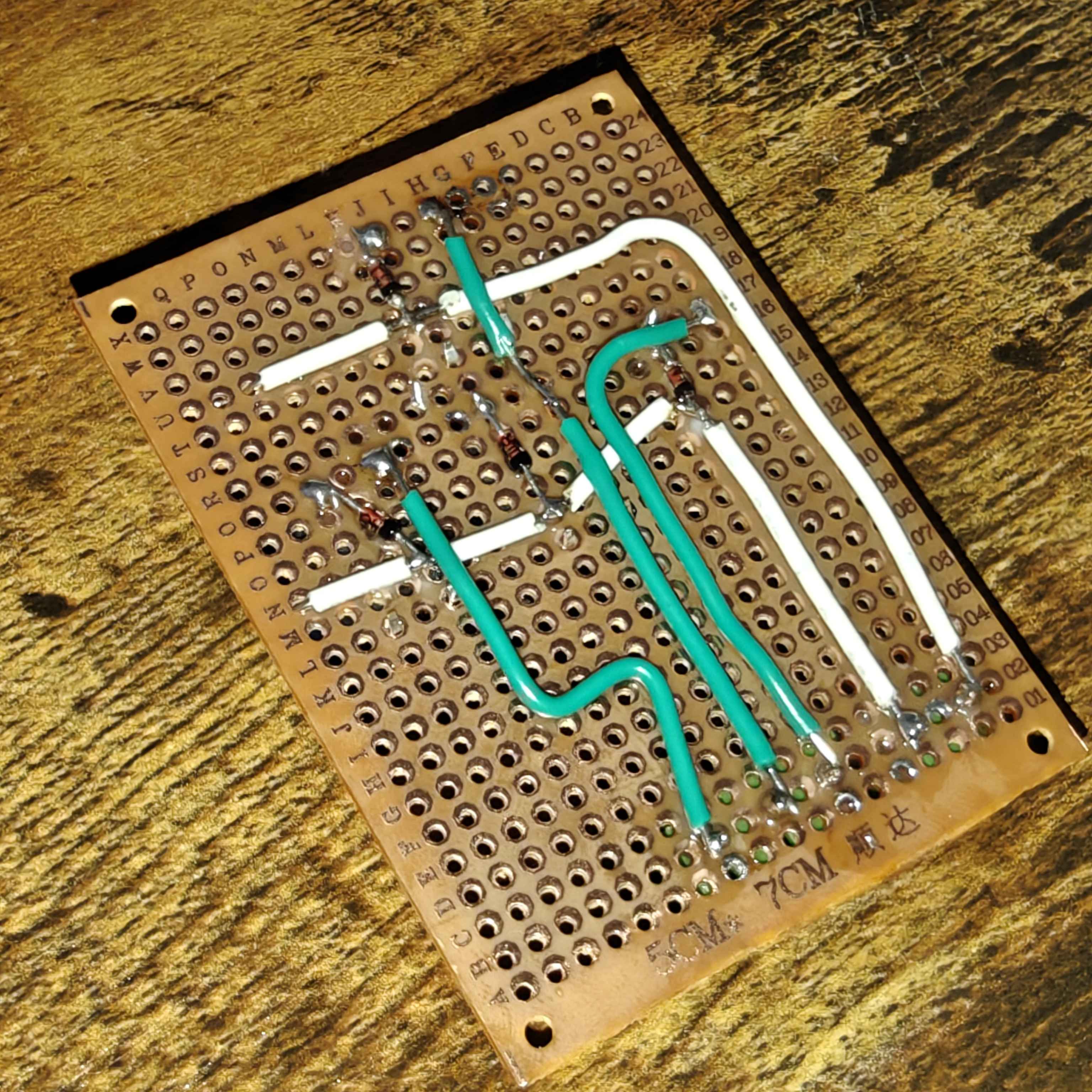
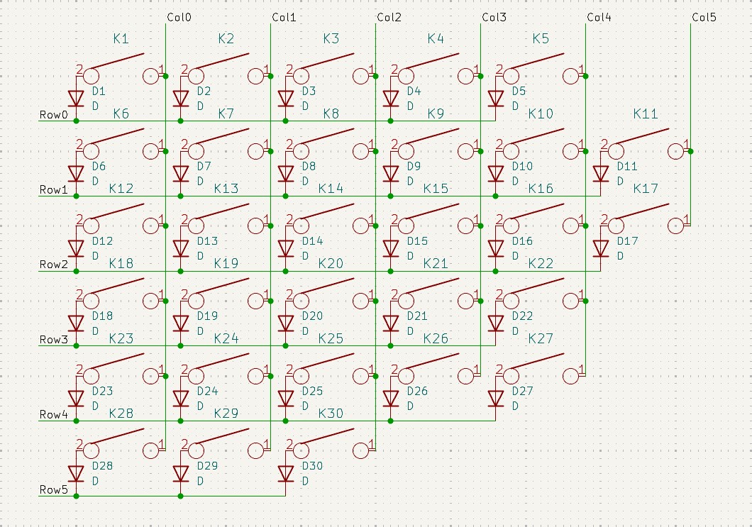
Here is the schematic I used. Observant viewers will notice SW32 and SW36 is missing in the finished prototype board. This is because ZMK still needs to see switches that don't exist, but you can assign their function as 'none' — which stops the key from being scanned.
It took some finicking about, but I eventually got the ZMK firmware working on the nRF52840 ProMicro.
Hot tip (kinda): the "pro micro" board is actually defined as 'nice nano v1'. So, when you set up the ZMK build environment, make sure to select 'nice nano v1' as your board.
ZMK let's you do all sorts of stuff. You can setup macros, custom combos, make keys do different things dependong on how they're pressed and how long, and different layers. I'm excited to learn more about the firmware.
Prototyping Switch Fit
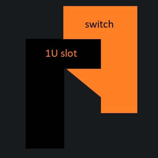
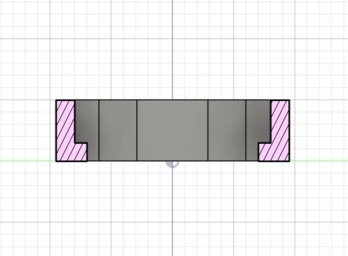
Mechanical switches have a 'lip' that latches onto the case. You can see in this image the operation of the latch mechanism. The first thing I needed to get right was the size and fit of this latching machanism. If the latch is too loose, the switch will wiggle around and feel mushy. If it's too tight, it will be difficult to insert the switch into the case — or the switch would break.
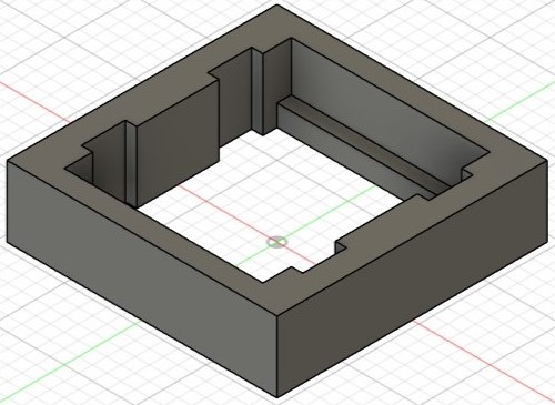
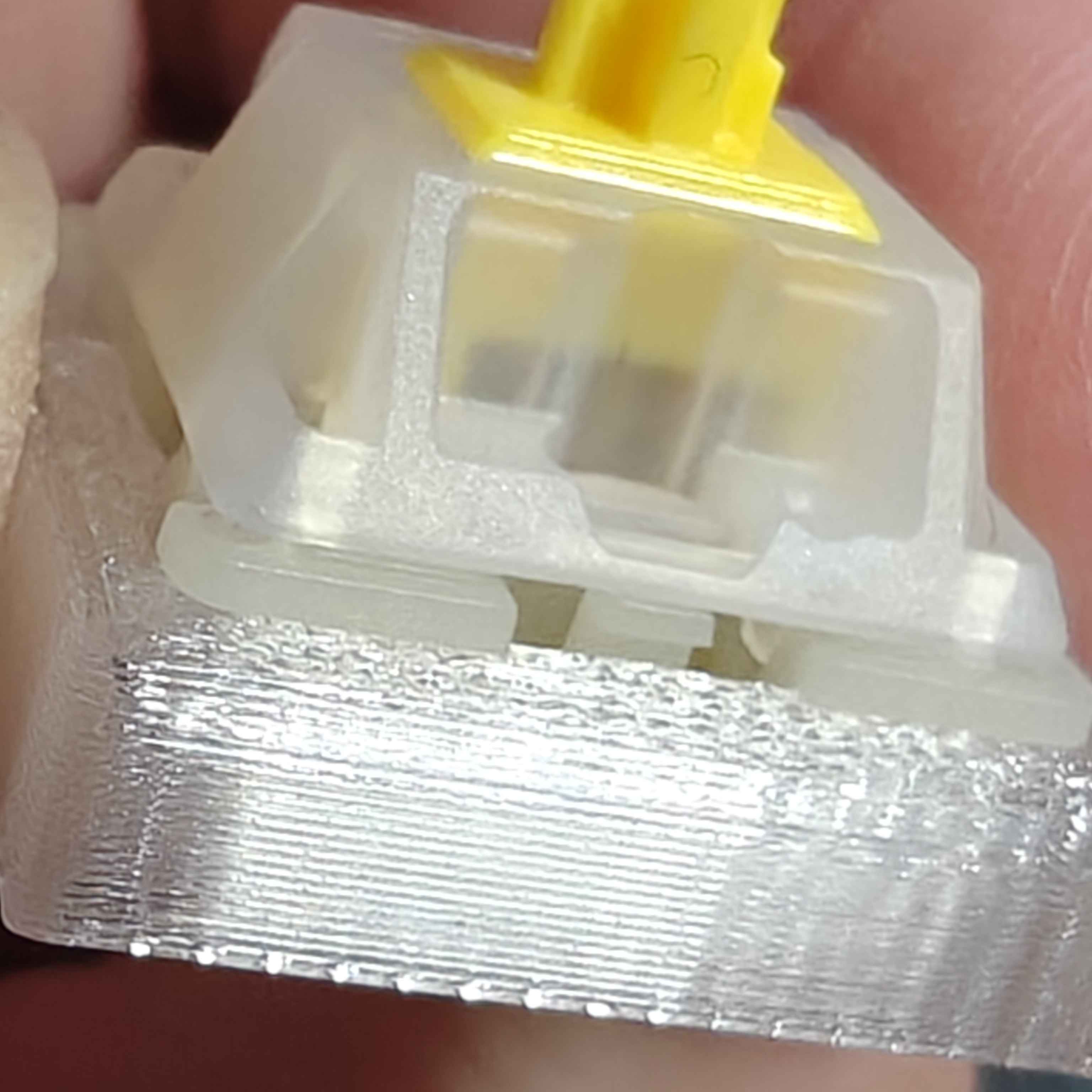
Eventually, I was able to create a functional design — nice and snug. The top of the switch is flush with the top of the case; this is important because it allows for a consistent keycap height across all keys.
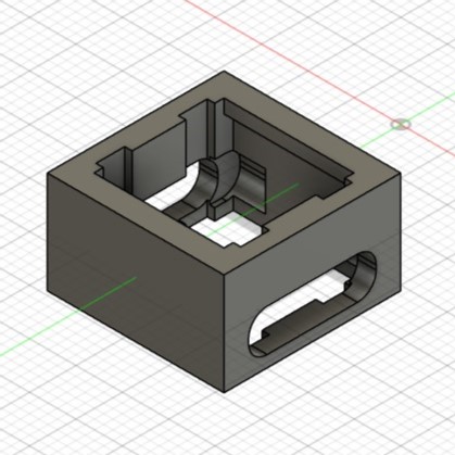
Prototyping Magnetic Connectors
The fit for the space bar magnetic connector took some iterations, but I eventually got a design that was nice and flush with the switch plate. There is very little wiggle room when two switches are connected, which is good for the feel of the keyboard.
The magnets are quite strong, so the space bar module is securely connected to the main module.
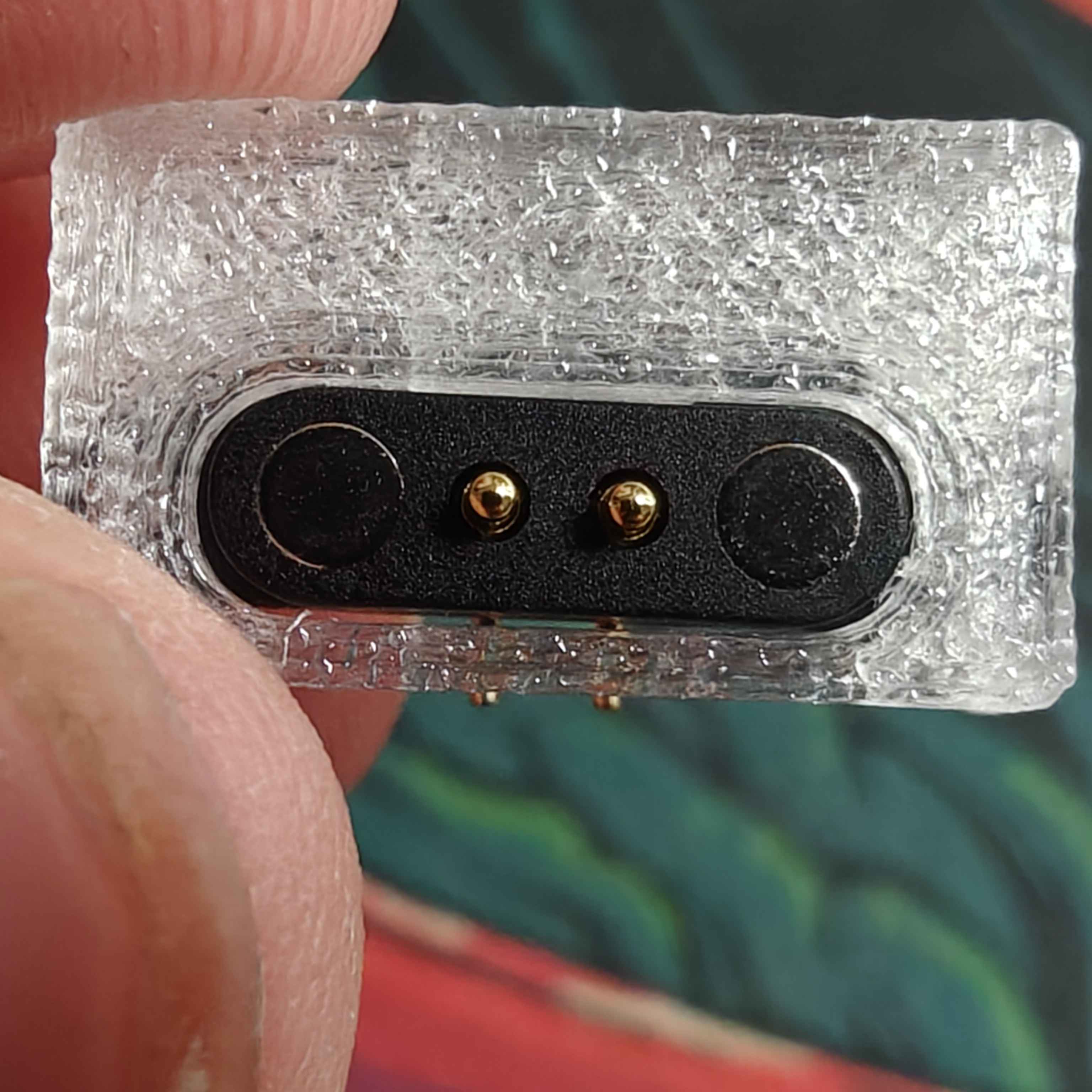
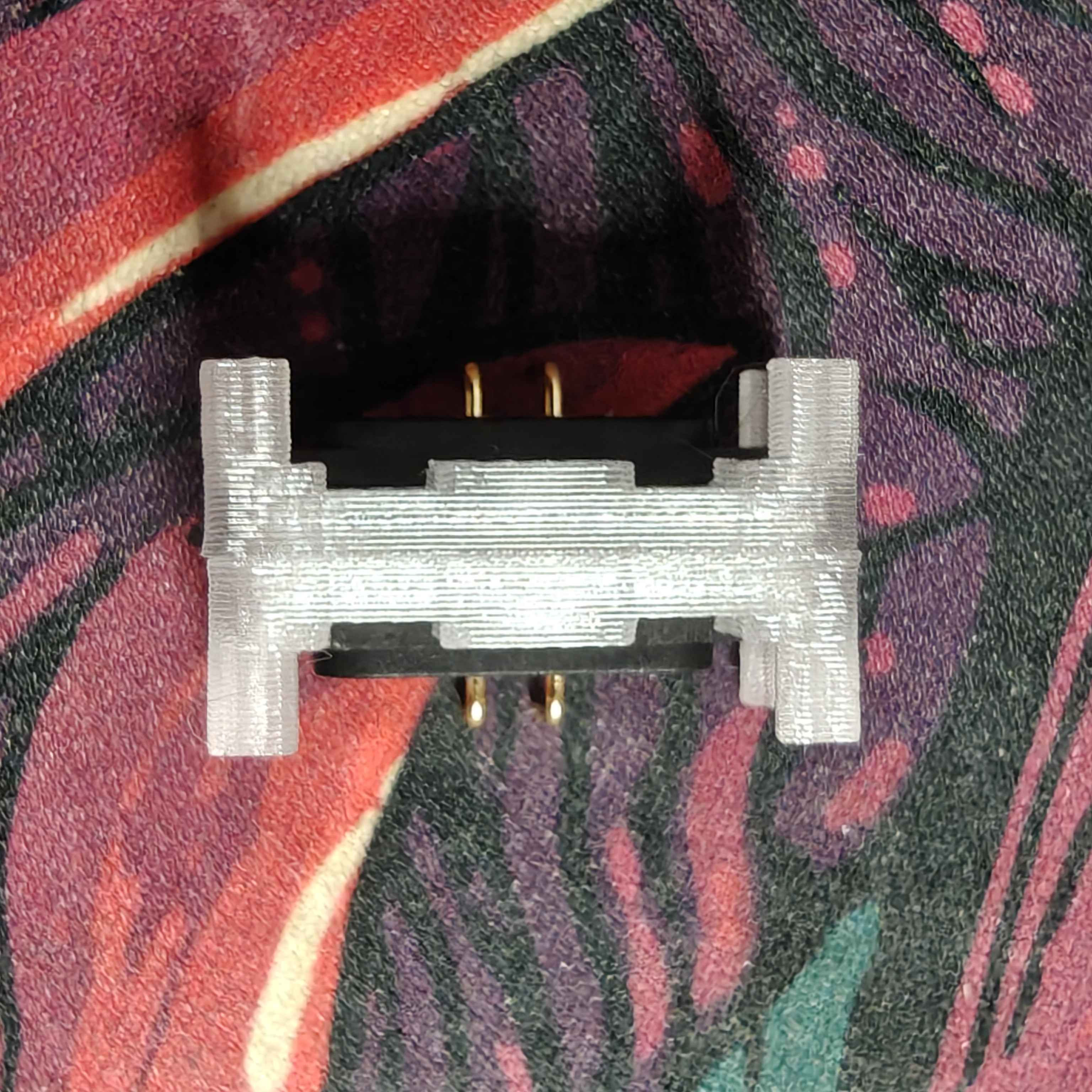
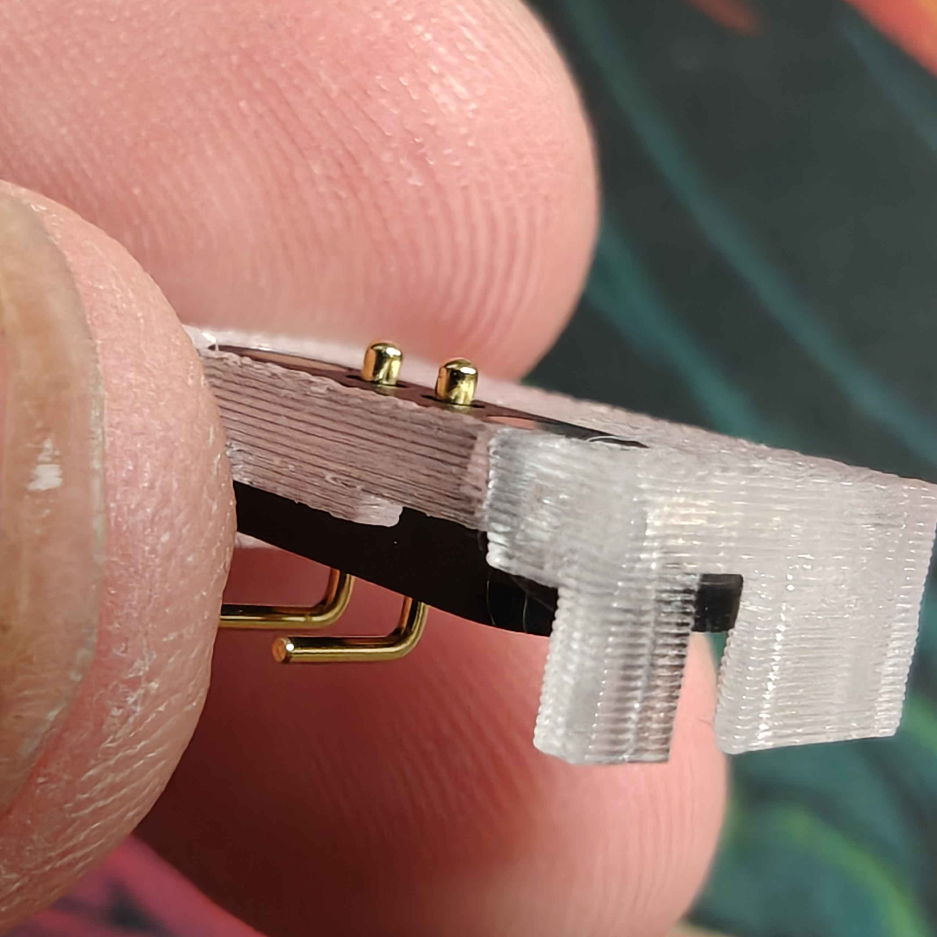
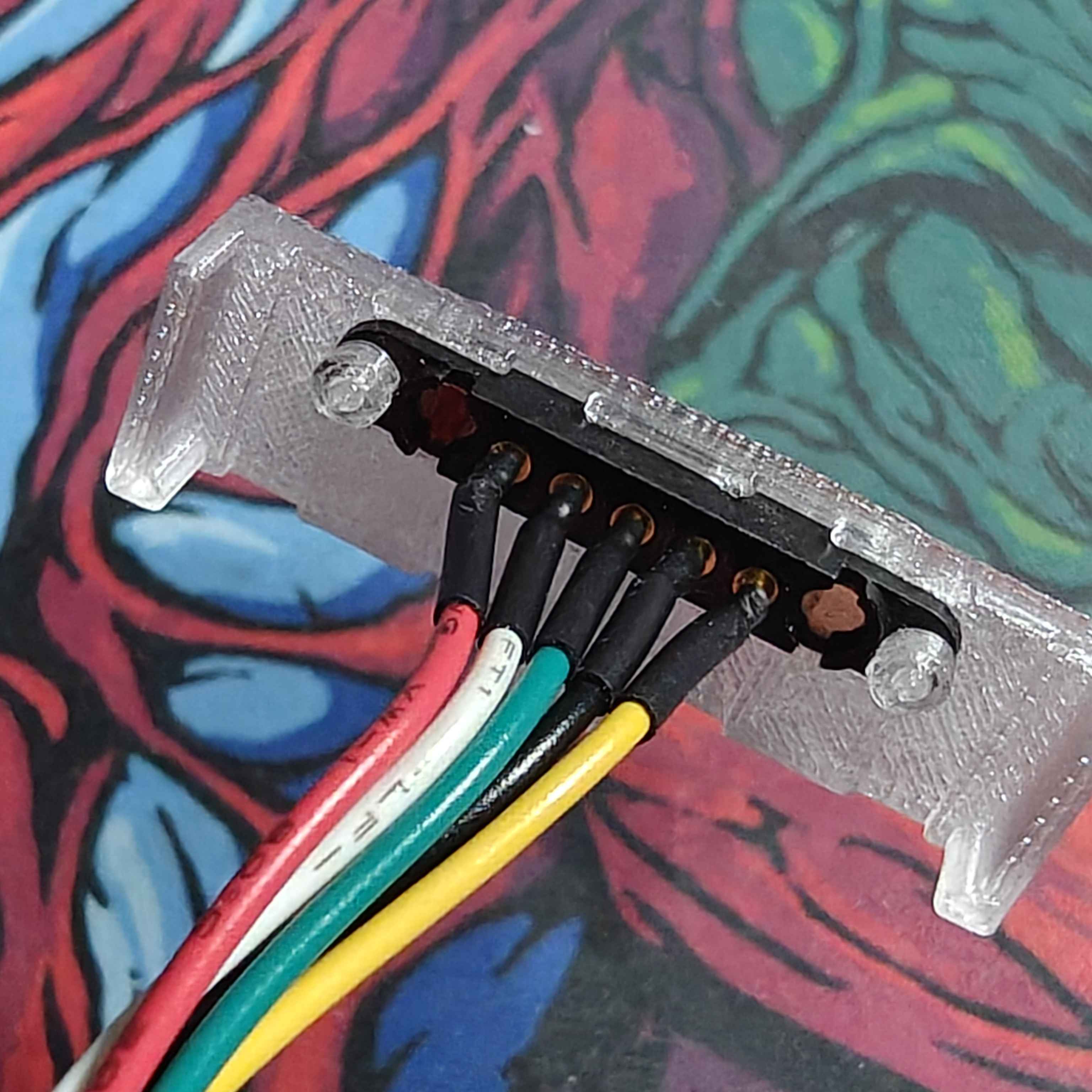
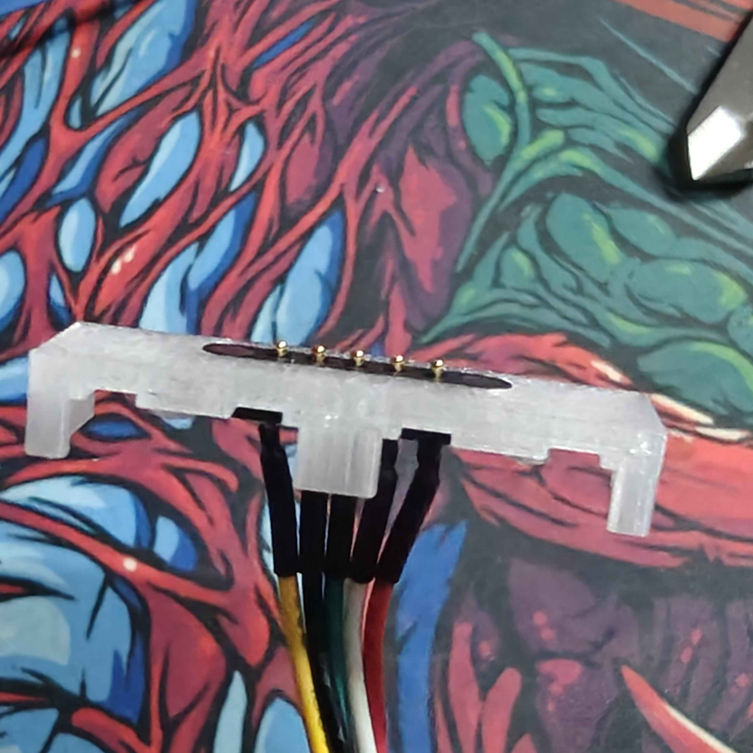
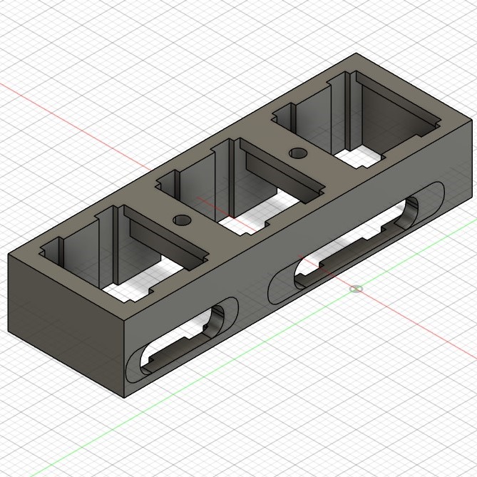
I also needed to make a good fit for the other, longer, 5 pin connector.
This fit is slightly different. To ensure the magnetic connector stays tightly in place, I added a pole and a cap to it. The cap is fit using friction and helps the connector stay in place when connected and disconnected.
3D Print Prototype
Since I had both connectors prototyped, I can start making a full 3D print for a prototype keyboard. The board is, also, made up of 3 components — the master, the auxilary, and the spacebar. This way, I can face and solve issues I'd face in the full keyboard design.
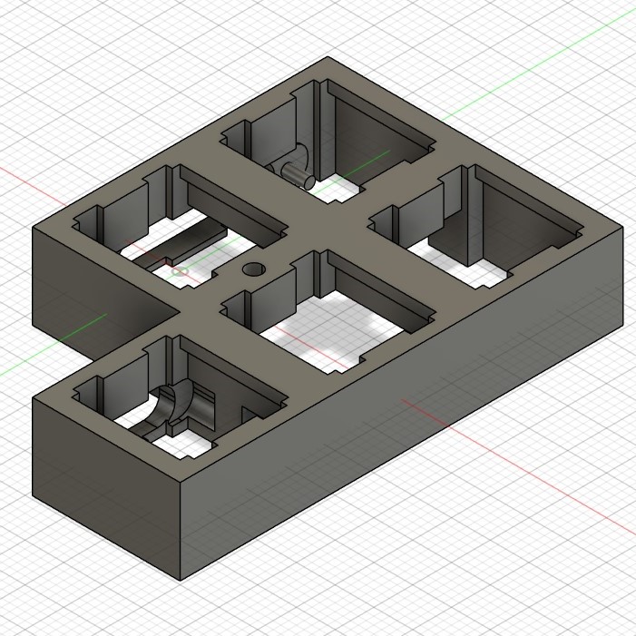
This is what the full design looks like.

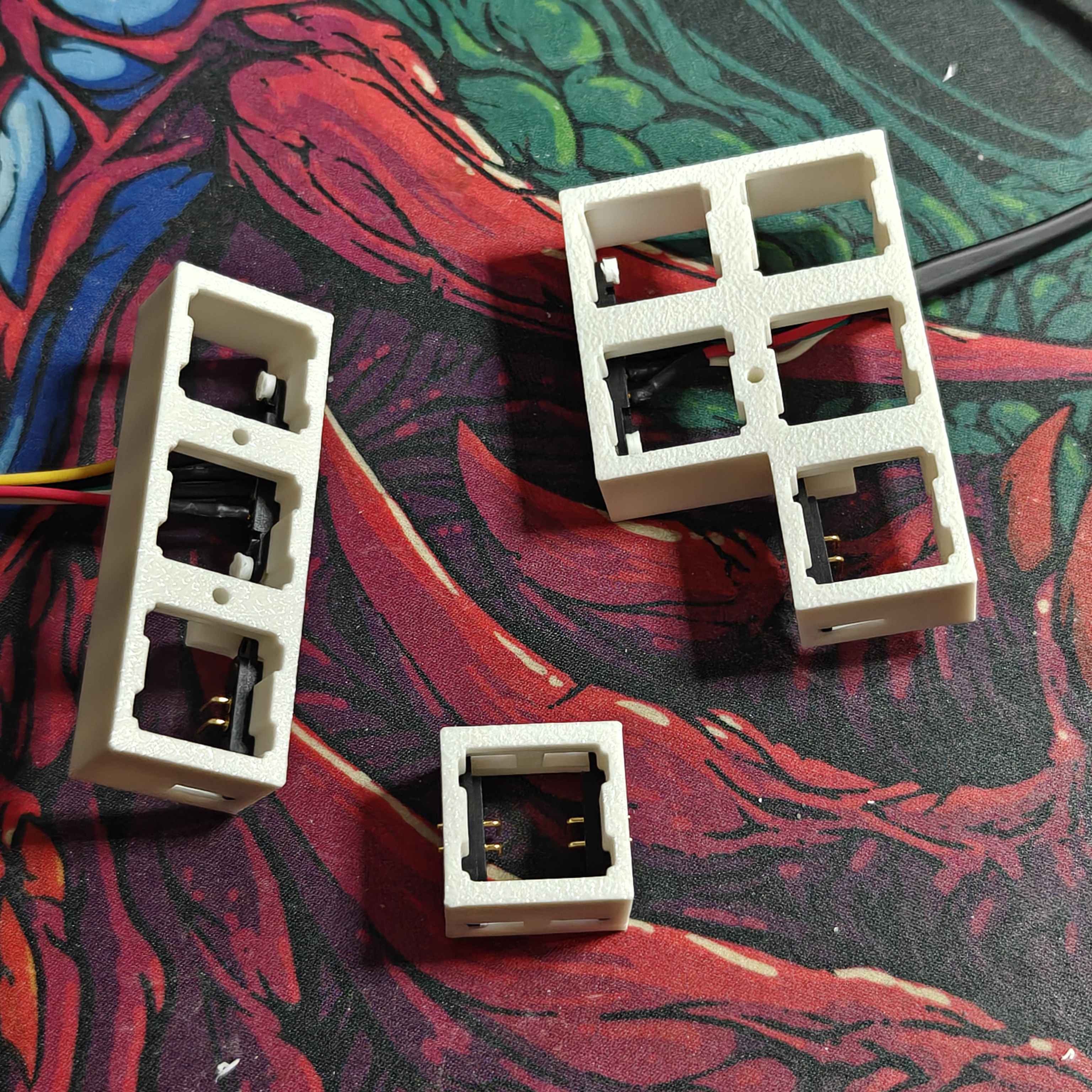
First Non-Functional Prototype
So exciting! After some minor changes from the original [above] design, I've got a non-functional prototype I'm happy with!
Here's some photos:
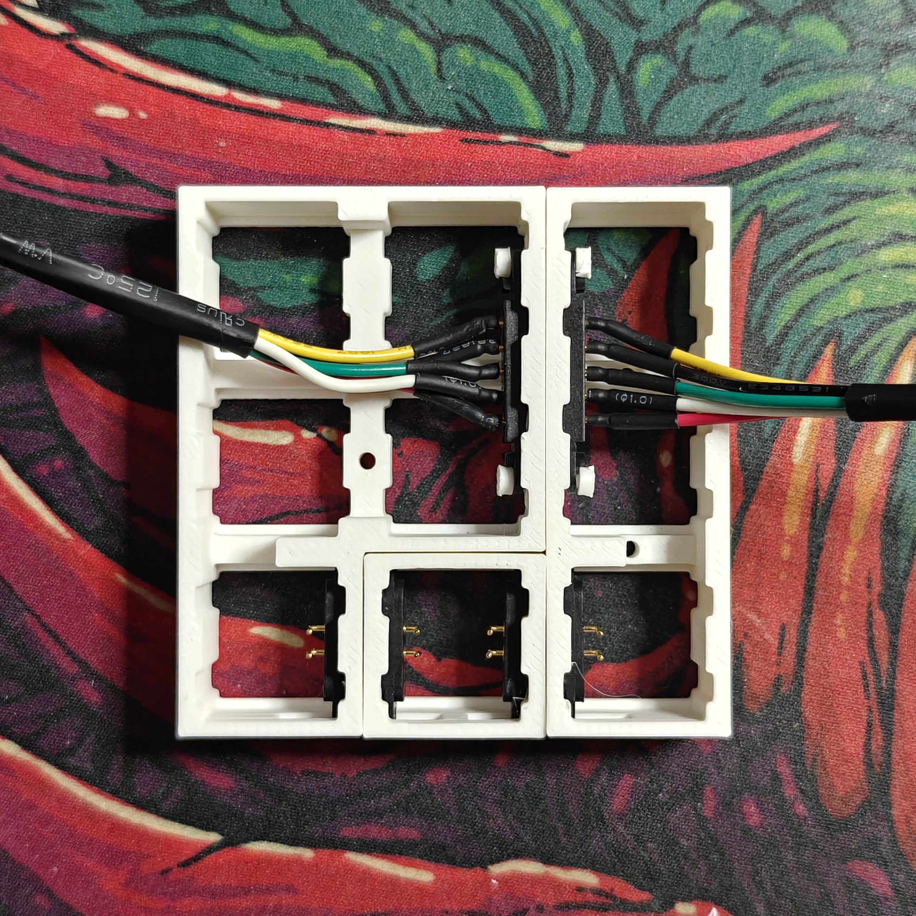
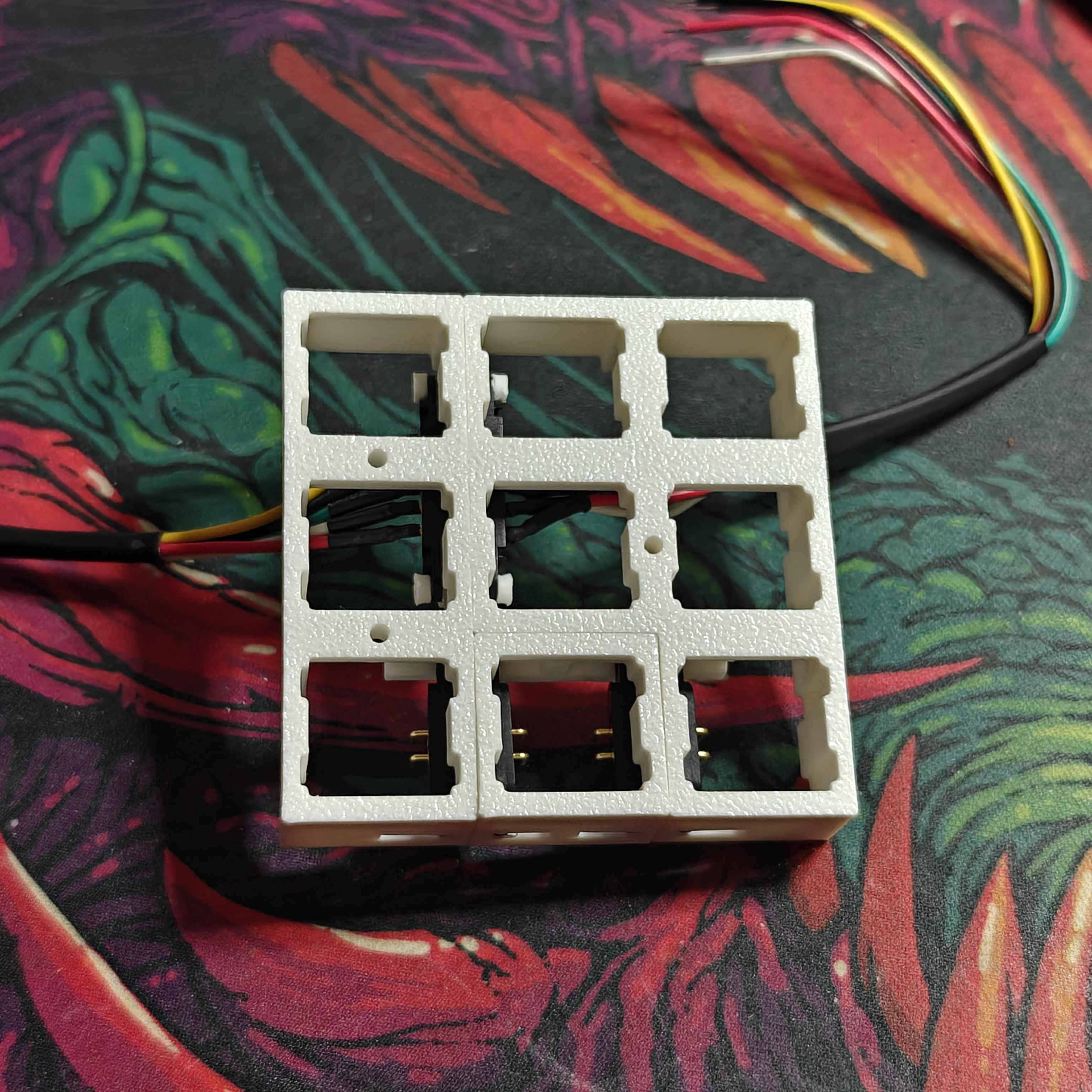
Fully assembled it looks like this:
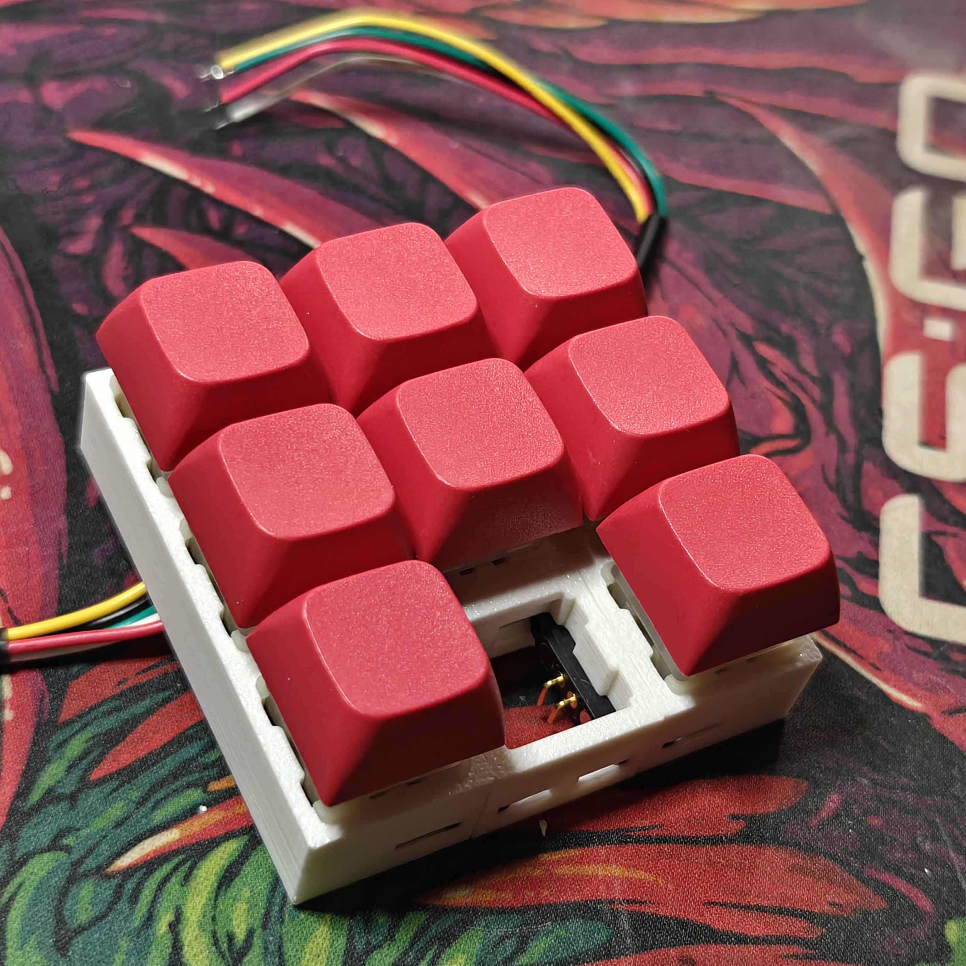
Overall, I'm happy with where the prototype is headed. They key spacing is really seamless and consistent — no awkward key gaps. The magnets are strong and hold the keypads well; however, the modules don't yet have any real weight to them. This could be a problem, but, for now, the magnets are great! For the fullsize keyboard, I have some extra neodymium magnets to help with the added weight. I'll need to adjust this design to accommodate for a circuit board later, but since this is only a non-functional prototype I don't need to worry about that right now.
There are a few issues this prototype helped point out.
I need to position the magnetic connectors lower down. The PCB mounting feet on the switches come very close to interfering with the magnetic connectors. Most of them fit but all of them come very very close to not fitting. On the single key module, the switch doesnt fit at all — switch mounting feet clearance issue.
Also, the install of the magnetic connectors is particulary difficult. I need to rethink how I want to hook them in. The smaller magnetic module fits pretty well using friction, but the longer ones need rods and caps. The way these rods print, because of their small size, is very tempermental. Printing the model on the rod side would improve their quality, but would also make them really prone to snapping off. My 3D printer hasn't been serviced or calibrated in a long time, so maybe servicing the thing could help? I'll do that when I have some more free time.
Finally, I accidentally printed this off with a mirrored design. Yeaaaaah kinda silly :p — I can fix this easily though.
3D Design
They way the keys are spaced on the keyboard is a bit weird. Some keys are longer, some are offset from the grid. Weird.